A linear encoder is a device that uses one or more motors to provide rotational input to a drive shaft and produces linear motion as output. Linear encoders are widely used in robotics, computer numerical controlled (CNC) manufacturing, and industrial automation systems.
The main difference between the typical mechanical encoder found in banks of robotics controllers is that it has an on-off operation with the “on” state being imparted by a magnet attached to the rotor, while the “off” state is caused by some other means such as mechanical contact or force applied by vacuum. This makes for efficient power consumption if no external energy source is needed for decoding. Many encoders are used in disk drives.
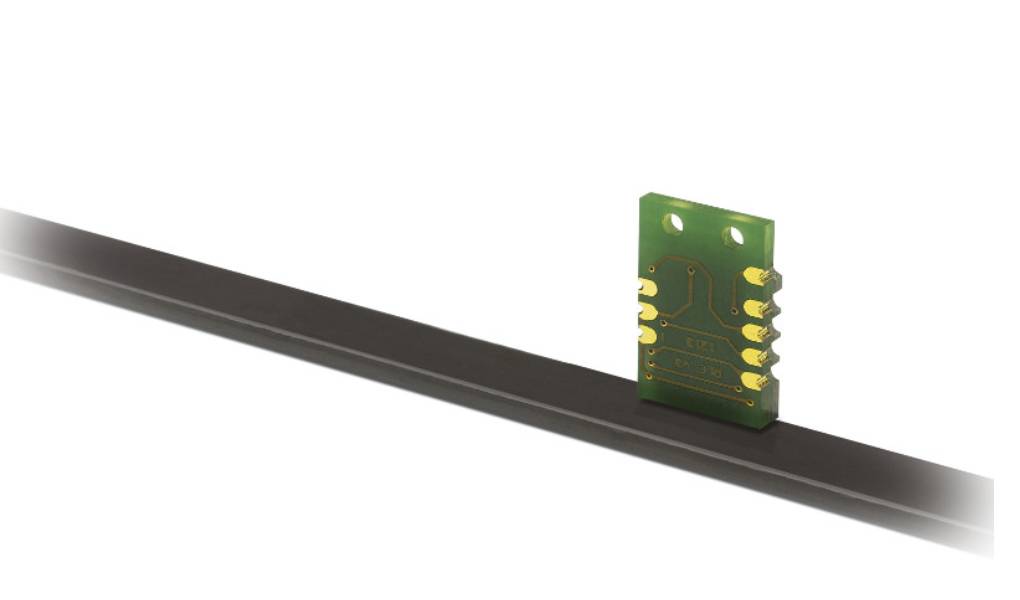
Analog and digital outputs can be used for more complex applications; for example, Bosch proportional valves can operate with a two-conductor digital HART protocol via the “extended linearization” method. In addition to the BNO055 magnetic type, many other analog and digital encoders are produced.
The most common variety are optical linear encoders, which use an infrared LED and a phototransistor together with the well-known principle of photoelectric conversion to convert the position of the motor’s output shaft into an electrical signal on a pair of conductors (the outputs).
What exactly is the linear encoder?
The linear encoder is a device that uses one or more motors to provide rotational input to a drive shaft and produces linear motion as output. Linear encoders are widely used in robotics, computer numerical controlled (CNC) manufacturing, and industrial automation systems.
The main difference between the typical mechanical encoder found in banks of robotics controllers is that it has an on-off operation with the “on” state being imparted by a magnet attached to the rotor, while the “off” state is caused by some other means such as mechanical contact or force applied by vacuum. This makes for efficient power consumption if no external energy source is needed for decoding. Many encoders are used in disk drives.
Analog and digital outputs can be used for more complex applications; for example, Bosch proportional valves can operate with a two-conductor digital HART protocol via the “extended linearization” method. In addition to the BNO055 magnetic type, many other analog and digital encoders are produced.
The most common variety are optical linear encoders, which use an infrared LED and a phototransistor together with the well-known principle of photoelectric conversion to convert the position of the motor’s output shaft into an electrical signal on a pair of conductors (the outputs).
How does a linear encoder work?
Linear Encoder is a kind of device that is widely used in robots, disk drives, and other kinds of automation systems. In the linear encoder, the output shaft is rotated by the motors using gears.
The gears are contained inside a box which is called the encoder. The rotating shaft in the encoder is fixed at one end of the box and rotates inside that box with the help of gears. The output shaft is rotated together with this output shaft, and then it moves at a certain angle to a certain direction and goes outside of the box as shown in the figure.
When the shaft is outside the box, it will be blocked by some of the stops, and it will not rotate further. The stops are fixed to be able to rotate inside the box with the help of gears. The signal between the motor and motor controller is a two-phase signal. The first phase tells that the output shaft is on, and the second phase tells that the output shaft is blocked. This two-phase signal will send to our PLC system through Modbus protocol, and we can drive our robot according to this signal easily.
Incremental linear encoder
An incremental Encoder is a kind of device that is widely used in robots, disk drives, and other kinds of automation systems. The term ‘increment’ actually means adding up. For example, if we turn 15 degrees to the left and add it with the last value, which is 15 degrees to the right, then the Increment Encoder will count 20 degrees. Generally, the Increment Encoder can count from 0 to up to 63,000 so that it can work with most of the automated control systems easily.
There are two kinds of incremental encoders: Non-Rotary Incremental Electro-Magnetic Linear Encoder and Rotary Incremental Optical Linear Encoder. Both of them have the same principle.
In the Non-Rotary Incremental Electro-Magnetic Linear Encoder, a magnet is attached to the shaft, and it has two stators on each side. The two stators will tell an electrical signal as they are moved by this magnet. One set of signals is used to count forward, and another set of signals is used to count backward. As such, we can count the number of rotations in both directions. In addition, we can also count the direction by examining these signals easily. For example, if we turn 15 degrees to the left and add it with the last value, which is 15 degrees to the right, then Increment Encoder will count 20 degrees (=15+15).
How does a magnetic linear encoder work?
The magnetic linear encoder is a kind of device that is widely used in robots, disk drives, and other kinds of automation systems. In the magnetic linear encoder, the output shaft is rotated by the motors using gears.
The gears are contained inside a box which is called the encoder. The rotating shaft in the encoder is fixed at one end of the box and rotates inside that box with the help of gears. The output shaft is rotated together with this output shaft, and then it moves at a certain angle to a certain direction and goes outside of the box, as shown in the figure.
When the shaft is an outside box, it will be blocked by some of the stops, and it will not rotate further.
Also Read: The Biggest Challenge For Brands Will Be Attribution Systems